-

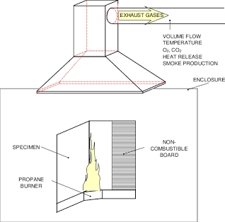
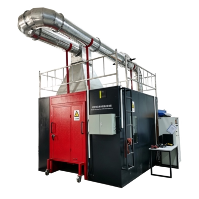
- Single Burning Item (SBI) Test System Diagram

-

- Single Burning Item (SBI) Test Apparatus System Architecture Diagram Reference
-
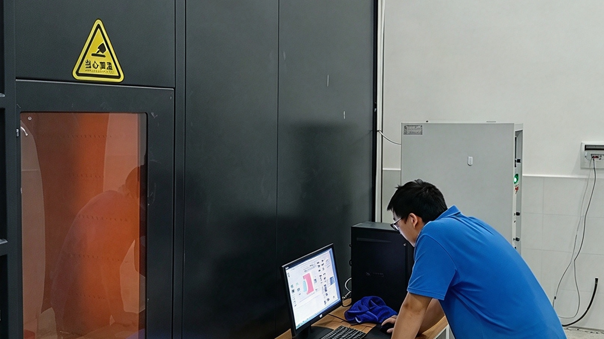
- Single Burning Item SBI Test System

Learn BRT’s Single Burning Item (SBI) Test System
1. General Requirements & Preparation
Before initiating the SBI test sequence, test operators must observe critical timing and environmental conditions:
- Conditioning Limit: The complete testing procedure must be executed within 2 hours after removing the specimen from the conditioning environment.
- Thermal & Equipment Equilibrium: All electronic instruments, pumps, and sensors must be switched on with sufficient warm-up time to reach thermal equilibrium before calibration or testing.
- General Electronics: A minimum of 30 minutes pre-heating is recommended.
- Gas Analyzers (O2 & CO2): Gas analyzers require significantly longer stabilization time; it is recommended to keep them continuously powered on.
2. Step-by-Step Testing Timeline & Operations
The operational process follows a precise chronological timeline under specified exhaust flow rates:
A. Flow Rate Adjustment & Pre-Test Baseline
- Exhaust Volume Flow: Set the exhaust volume flow V 298 (t) to (0.60 ± 0.05) m³/s. The flow rate must be continuously maintained within 0.50 m³/s to 0.65 m³/s throughout the entire test. (Note: Manual or automatic adjustments may be required during testing due to heat output fluctuations).
- Temperature Stabilization (at least 300 s): Continuously record thermocouples T1, T2, and T3 in the exhaust duct along with ambient temperature.
- Ambient Temperature: Must remain within (20 ± 10) °C.
- Duct Temperature: Must not deviate by more than 6 °C from the ambient temperature.
- Pilot Flames & Pre-Test Conditions: Ignite pilot flames (gas supply changes must not exceed 5 mg/s). Record ambient pressure (Pa), ambient relative humidity (%H2O), and baseline temperature.
B. Execution Timeline (t = 0 s to End of Test)
- t = 0 s (Test Start): Initiate the chronometer and automated data acquisition system.
- t = (120 ± 5) s (Auxiliary Burner Ignition): Ignite the auxiliary (secondary) burner and adjust the propane mass flow rate (mgas) to (647 ± 10) mg/s before t = 150 s.
- Baseline Measurement: The period between 210 s < t < 270 s measures the baseline for the Heat Release Rate (HRR).
- t = (300 ± 5) s (Main Burner Switch): Switch the propane gas supply from the auxiliary burner to the main (primary) trolley burner to expose the test specimen to direct thermal attack.
- t = 300 s to 1560 s (Specimen Exposure Period): Observe and manually record combustion behavior over a nominal exposure period of 1,260 seconds (performance evaluation is based on a 1,200 s window).
- t ≥ 1560 s (Test Termination): Shut off the propane gas supply to the burner and stop automatic data logging.
- Post-Test Record (≥ 1 min after extinction): Record final baseline conditions (light transmission, O2 and CO2 mole fractions) once any remaining specimen flaming is completely extinguished.
3. Visual Observations and Manual Data Logging
During testing, an observer equipped with an event-logging chronometer must visually monitor and record critical fire behaviors:
A. Lateral Flame Spread (LFS)
Record the occurrence of sustained flames reaching the far edge of the specimen’s long wing at any height between 500 mm and 1000 mm. The criterion requires sustained flaming at the boundary for a minimum of 5 seconds.
B. Flaming Droplets and Particles
Continuous high-resolution video recording is required if flaming droplets or particles are anticipated.
- Time & Location Window: Recorded only within the first 600 seconds of exposure when droplets/particles fall onto the trolley floor outside the burner zone (< 0.3 m radius from the corner line).
- Categorization:
- Short-duration: Flaming particles that burn for ≤ 10 seconds.
- Persistent: Flaming particles that burn for > 10 seconds.
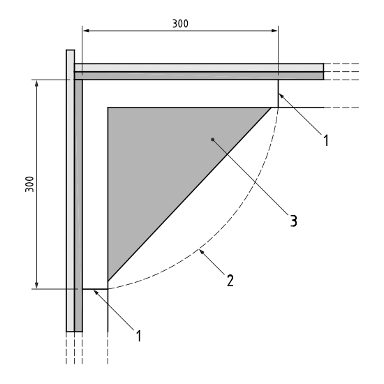
Key:
1. obstruction plate I U-profile
2. burner zone border
3. burner
C. Other Critical Events
Operators must record occurrences such as surface flash, smoke escaping into the test room, specimen collapse, or joint failure at backing board corners.
4. Automated Data Acquisition Parameters
The data acquisition system must automatically sample and store measurement readings every 3 seconds:
| Parameter | Symbol | Measurement Location / Notes |
|---|---|---|
| Time | t | Elapsed time in seconds (t = 0 s at start) |
| Propane Mass Flow | mgas | Mass flow rate supplied to the burner (mg/s) |
| Differential Pressure | Δp | Measured across the hemispherical probe in duct (Pa) |
| Light Attenuation | I | White light receiver signal in exhaust duct (%) |
| O2 Mole Fraction | xO2 | Gas sampling probe in the general measuring section |
| CO2 Mole Fraction | xCO2 | Gas sampling probe in the general measuring section |
| Ambient Temperature | T0 | Measured at the air inlet near trolley base (K) |
| Duct Temperatures | T1, T2, T3 | Exhaust duct thermocouples (K) |
5. Early Termination Criteria & Equipment Protection
To protect testing equipment and maintain validity, operators should understand early termination protocols:
- Choking / Flame Disturbance: Stop the main burner immediately if fallen specimen material enters the burner’s sand-bed and severely distorts or chokes the flame. Tests terminated early are invalid for Euroclass classification.
- Thermal Protection Thresholds: Operators may consider early termination if parameters exceed maximum limits:
- Heat Release Rate (HRR): Exceeds 350 kW instantly, or 280 kW for more than 30 seconds.
- Exhaust Duct Temperature: Exceeds 400 °C instantly, or averages above 300 °C for over 30 seconds.
SBI Test Key Calculated Parameters and Euroclass Ratings
Once the test concludes, the system’s advanced software automatically processes the raw data to determine final performance indexes. These calculations are vital for assigning material ratings under EN 13501-1:
- HRR & THR (Heat Release Rate & Total Heat Release): Measures how rapidly and how much energy the burning product contributes to a fire.
- FIGRA (Fire Growth Rate Index): Derived from HRR data, indicating how fast the fire grows.
- SPR & TSP (Smoke Production Rate & Total Smoke Production): Quantifies visibility loss and smoke hazards generated during combustion.
- SMOGRA (Smoke Growth Rate Index): Evaluates how rapidly smoke accumulates during the critical early stages of the fire.
Conclusion
Mastering the BS EN 13823 Single Burning Item (SBI) test procedure ensures that building products meet stringent European safety standards. By maintaining strict control over calibration, specimen conditioning, and real-time data analysis, manufacturers can reliably classify their materials and bring safe, compliant products to the global market.
About EN 13823:2020+A1:2022 (Single Burning Item SBI Test)
Key Technical Topics & Requirements
- Scope & Product Applicability: Governs building products (excluding floorings and designated regulated goods). Note that linear items such as pipes, ducts, and cables often require specialized mounting rules.
- Test Principle: Exposes a vertically mounted test specimen to direct thermal attack from a single burning item (propane burner) within a standardized test room and apparatus.
- Calibration & Calculations: Includes computation procedures (Annex A), repeatability/reproducibility metrics (Annex B), and mandatory calibration routines (Annexes C and D).
- Safety Protocols: Emphasizes critical safety warnings regarding toxic smoke emissions, propane fuel supply lines, and precise ignition/extinguishing procedures, recommending strict facility safety protocols.
Core Measured Parameters & Indices
| Parameter / Index | Description |
|---|---|
| THR600s | Total heat release during the first 600 seconds of flame exposure. |
| TSP600s | Total smoke production during the first 600 seconds of flame exposure. |
| FIGRA0.2MJ / FIGRA0.4MJ | Fire growth rate indices used for Euroclass classification. |
| SMOGRA | Smoke growth rate index. |
| LFS | Lateral flame spread across the specimen wing. |
Test Facility & Chamber Specifications
| Facility Requirement | Standard Specification |
|---|---|
| Test Room Inner Height | (2.4 ± 0.05) m |
| Test Room Floor Area | (3.0 ± 0.05) m × (3.0 ± 0.05) m |
| Apparatus Components | Specimen trolley, main & auxiliary burners, exhaust hood, ducting, and white light photometer system. |
Practical Applications & Target Users
- Fire Testing Laboratories: Conduct rigorous SBI testing to generate repeatable, compliant reaction-to-fire data.
- Product Manufacturers: Generate empirical test evidence to substantiate performance claims and secure Euroclass classification under EN 13501-1.
- Certification & Notified Bodies: Assess product compliance to facilitate CE marking and official national approvals.
- Fire Safety Engineers & Specifiers: Evaluate quantified fire performance data to select safe and compliant building materials.
- Regulators: Uphold harmonized fire safety classification frameworks across the EU and EFTA markets.


A very accurate explanation, consistent with the official EN 13823:2020+A1:2022 documentation.
[…] step-by-step guide to the SBI test procedure (EN 13823) covers the chamber setup and timeline in detail, and the single burning item test system implements […]